
How to build a light scissor extender rig
Please note: This project was submitted by FrightProps customer Darin Cleveland. It has not been verified by FrightProps and we cannot provide support on this project.
Description:
This instructional will show you how to build an air driven scissor extender rig that will quickly extend and retract a lightweight prop. The extender shown in this instructional is able to extend three feet and can move a five pound prop, but those statistics will change depending on how you modify your version.
This extender, with rods 12’ long (11.5’ between the centers of the far holes) extends 9 inches per arm “segment” (two rods crossing). The rig in this instructional uses four arm segments, so it 36 inches long.
This rig is intended to be used with props less than 5 pounds in weight, such as a foam rat, large spider, dog, some sort of large mask, or a caped ghoul.
Adding segments will increase the extension distance of your rig but will also increase the force placed on the rig due to the physics of leverage. If you modify this rig’s design to make it longer, it is recommended that you use a prop significantly less than 5 pounds.
Inversely, if you shorten the rig’s extension distance, a heavier prop may be used.
Why aluminum U-shaped tubing for the arm?
- U-shaped tubing is used instead of flat strips to prevent the arm from bending left and right.
- 8feet of this should cost less than ten dollars, so it’s quite cheap.
- aluminum is much lighter than steel. In this design, steel tubing would be too heavy for the drawer sliders to handle. This mechanism’s design accounts for lightweight props only.
Required Tools:
- Tape measure
- Some sort of masking tape
- Welder
- Metal saw (electric powered or hand saw. Electric is strongly advised)
- Metal grinder
- Drill (a drill press is recommended for straight holes)
Required Parts:
- 8 feet of ½ inch U-shaped aluminum mounting bracket (can be found in almost any hardware store)
- 8 feet of ½ inch square steel tubing (also can be found in almost any hardware store)
- Two, 1/2inch long bolts of 10-24 thread. (any sized bolt will work so long as it fits within the U-shaped aluminum, this is just the bolt used in this specific example. Apply this note for all nuts and bolts mentioned in this instructional)
- Eleven, 3/4inch long bolts of 10-24 thread. (if building more than four arm segments, purchase an extra three bolts per additional segment.)
- One, 2inch long bolt of 10-24 thread.
- At minimum, sixteen lock nuts of matching thread and diameter.
- At minimum, thirty six washers of matching diameter.
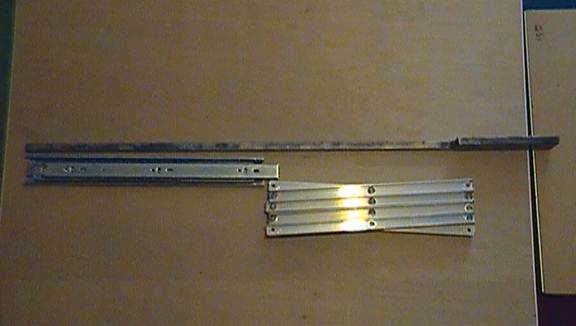
- A set of two 14inch long drawer sliders (can be found in many hardware stores)
- a power cord or trigger to power the cylinder solenoid
- an air compressor
- A piece of L-shaped rod, from ½ to ¾ inch width, aluminum or steel, only 2inches are needed.
Builder’s tip: in the case of small nuts and bolts, it is wise to purchase a handful of spares in each case, should you lose pieces, break them, or wish to add more to a project for extra stability.
FrightProps required parts:
- An air cylinder (cylinder used in instructional is a 4inch stroke 1 1/16 bore double-acting universal mount FrightProps cylinder . This bore of cylinder exerts more power than necessarily needed, so cylinders of smaller bore may be alternatively used.)
- A FrightProps cylinder hook-up starter kit (double acting, 1/4inch tubing, 12VDC (will require a 12VDC power source. 110VAC may be alternatively used). )
- A Pivot Bracket (if using the cylinder above, use a .25in hole x .38in opening) )
- A rod clevis (if using the same cylinder, 5/16 – 24)
- A quick connect with push on, ¼ tube size (to connect the system to your air compressor.)
- Two male connector push-ons with flow control, 1/4in tube
Optional Parts:
- A couple regular hex nuts of matching thread to be used as spacers
- Air regulator
- Any trigger, from motion sensor, step mat, or button activated.
*Total cost: approximately $185.00
*not counting the air compressor, air regulator, wood base board, or prop you wish to attach to the rig.
Important Notes:
- Please read through all steps before starting this project.
- Instructions may seem a little out of order at times. This is because everything built is based off of the size of the previous piece you built, to assure that everything fits.
- Don’t panic if your measurements are a little off at times. This pneumatic’s design comes with a lot of “wiggle room” due to its many moving parts.
- Remember that pneumatics can extort a lot of force and can be dangerous. Maintain a safe distance and keep your pneumatic rig away from objects and other people while it is powered on. When testing this prop for the first time, twist the flow control connectors almost all the way clockwise to test it at its slowest speed.
- Practice safety when modifying power cords. NEVER modify a power chord when it’s plugged in.
Step 1:
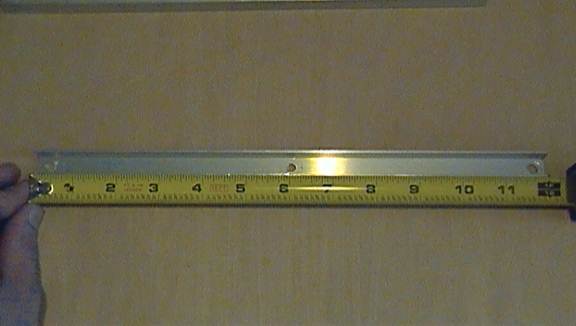
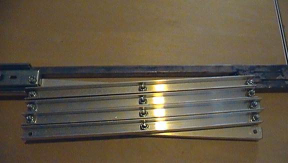
Cut a 12inch long piece from your 8 feet of U-shaped aluminum pipe.
Drill holes of the same diameter as your bolts in at the ends and center of your piece of aluminum pipe. It is very important that the center hole is centered exactly between the two outer holes (it’s ok if the holes are not perfectly centered on the bar itself)
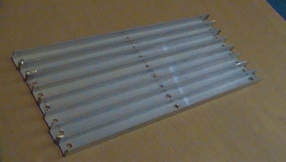
Create seven more pieces like this, totaling eight. Use the first piece as a guide by clamping it to the other pieces and drilling through the source piece’s holes into the new piece. This will assure that all your pieces are identical (again, the distance between holes is the important part, it’s ok if some pieces are a little shorter or longer than others).
Step 2:
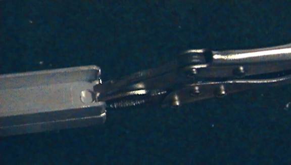
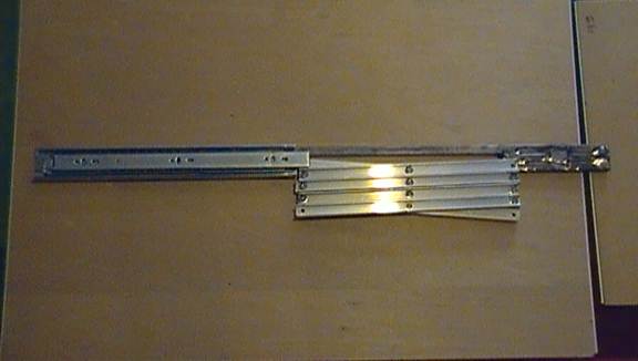
Pair the pieces together into arm sections by mounting them to each other by the center hole. Use the 3/4inch bolts.
Layer it as such: Bolt head, washer, first piece of aluminum, washer, second piece of aluminum, washer, lock nut.
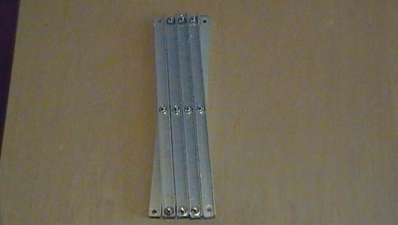
Tighten the lock nut to a point where the two pieces cannot wobble, but can still spin freely.
Mount your four arm segments to each other with the same sandwich of bolt, washer, lock nut, as described above.
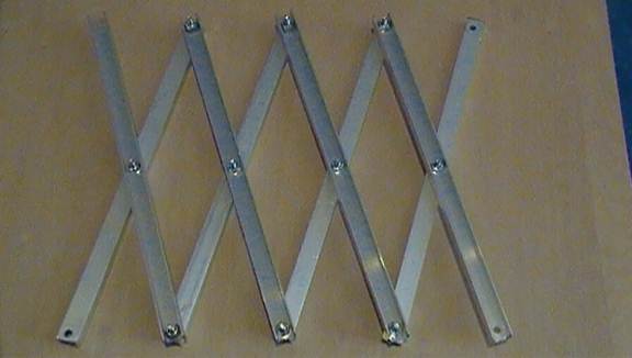
Your scissor extender arm should be able to retract and extend with minimal force. Loosen lock nuts if it needs to move more freely, and tighten them to eliminate wobble.
Step 3:
This is where measurements become inexact and you must rely on the dimensions of your other pieces to put it together properly.
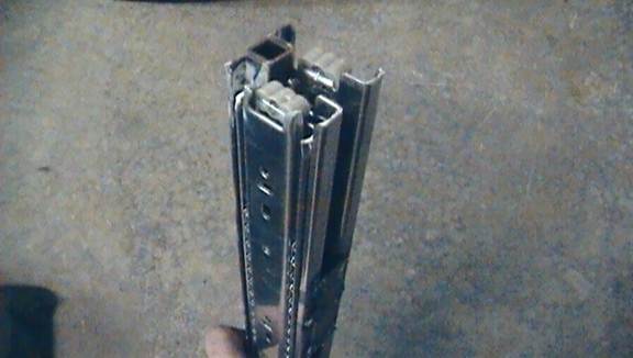
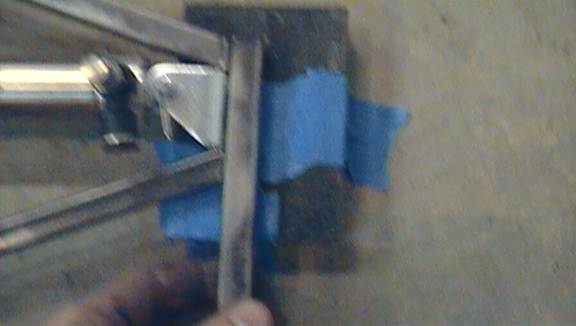
Cut the “mast” of your rig from the 1/2inch steel tubing. Its length should be the length of one of your drawer sliders (in this case, 14inches) plus the height of your scissor mechanism when it is fully retracted, plus however high you want your rig to be off the ground (at least six inches).
Step 4:
Now you need to figure out how far from the mast you need to mount your scissor mechanism. Make sure that whatever holes you drill to mount the scissor mechanism on are far from the mast enough that the scissor’s corners do not strike the mast. The corners will extend farthest when the mechanism’s arms are at a 45degree angle.
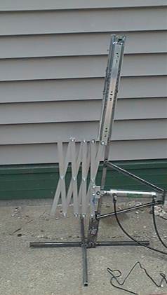
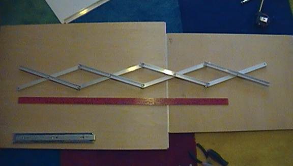
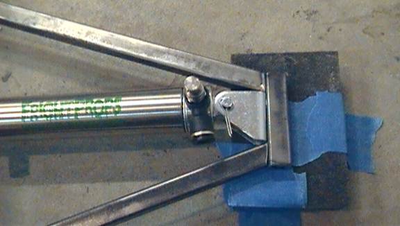
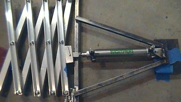
Your eventual goal is for it to look something like this:
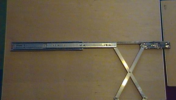
Note that half of the scissor mechanism will be lined up perfectly with the mast, and the other half (the “upper” half, as seen from the angle in the picture above) is offset from the mast half an inch (or slightly more, due to the washers between arm pieces).
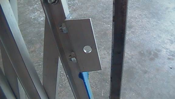
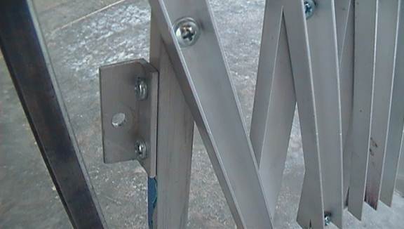
There are two holes here on which the scissor mechanism is connected. One which does not move, which is on the bottom, and one that that does move because it is drilled through the drawer slider.
Place the drawer slider on top of the mast as seen, keep it parallel with the mast (you will weld it in place later). Drill the hole through the drawer slider, again making sure that it is far enough from the mast that the scissor’s corner won’t hit it when rotating.
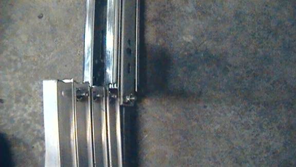
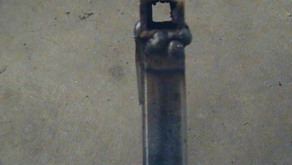
Once you have done this, weld two or three short sticks of 1/2inch steel tubing to the mast’s bottom. In the farthest stick, you will drill the stationary hole for the scissor mechanism.
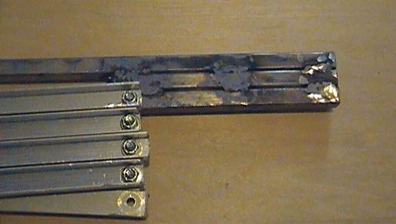
It is KEY that the bottom, stationary hole is just as far or farther from the mast than the moving slider hole. If the slider hole is farther from the mast than the stationary hole, the scissor mechanism will be angled downward and your prop will be forced into the ground. It’s okay, even preferable depending on your intent, to have the stationary hole farther out than the slider hole, as this will angle the scissor mechanism upwards a little. If anything, this will result in making it look like your prop is leaping out at someone.
Step 5:
Now you’ll weld the first drawer slider to the mast in the same position as you had it when you figured out where to put the holes. After you’ve figured out where to weld, grind away the top layer of metal where you intend to weld. Drawer sliders like this often have a glossy finish on top, and that will interfere with welding.
Weld the slider on its top, bottom, and middle on both of the sides which are in contact with the mast, but welding its entire length on is not necessary.
(a picture for this step is not supplied)
IMPORTANT: when welding the drawer slider to the mast, don’t weld for very long at a time. Take a break for the slider to cool down after every couple welds. If the slider heats up too much, it will warp and not slide properly.
Additional note: the man who built this example rig is by no means an experienced welder. Use other online guides to learn how to weld properly. That having been said, this simple rig does not require much skill in welding to get the job done.
Step 6:
Bolt your scissor mechanism to the slider and the stationary hole. Use the same principal as before, keep the lock nuts just loose enough to let thing rotate freely. You’ll have to use multiple lock nuts and/or washers to space the scissor mechanism from the drawer slider properly.
Test your rig so far. When you pull on your scissor mechanism to make it extend, the slider should extend and your scissor mechanism should move roughly perpendicular from the mast.
Step 7:
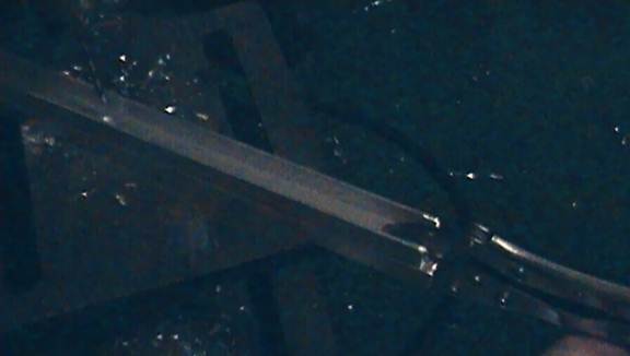
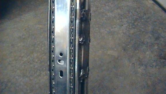
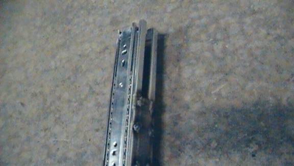
Now weld on the second drawer slider to the other side of the mast, mirror image it to the first. This second slider will add additional strength and stability to the mechanism.
You will be unable to weld the slider to the “inner” side of the mast, due to the narrow space between the two sliders. Compensate for this by taking a small piece of 1/2inch steel tube or a flat strip of steel (as shown in this example) and welding the two sliders to each other. Their stability will be greatly increased by bracing them against each other.
Remember to weld in short intervals, to prevent the sliders from overheating and warping.
Step 8:
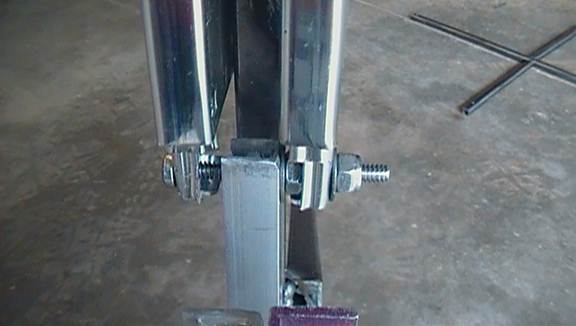
Temporarily remove your scissor mechanism from the slider hole. Use the first slider as a guide for putting a hole in the second slider. Once that hole is drilled, use your 2inch bolt to install the scissor mechanism between the two sliders. You will need a combination of lock nuts and/or washers and regular nuts to space the scissor arm evenly between them.
Step 9:
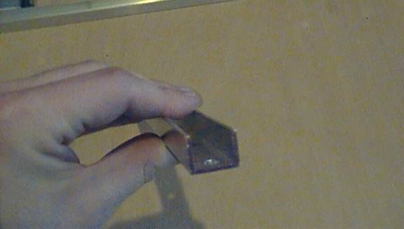
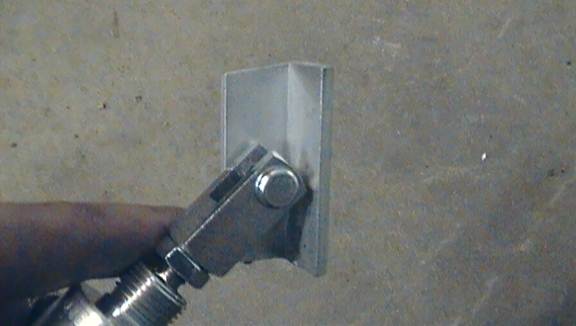
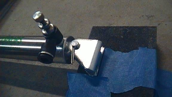
Take whatever L-shaped piece of material you have and cut it to about 2inches in length. Drill a hole through the center of one side. The hole needs to be equal diameter to the rod-clevis for your pneumatic. Install the L piece onto your rod clevis as shown bellow. This is the part of the pneumatic that will push your scissor mechanism.
Afterwards, install the pivot bracket to the bottom of your pneumatic cylinder.
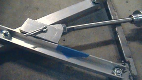
Step 10:
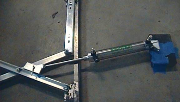
A massive amount of guess and check is required of this next step. Here is where you figure out exactly where to install your pneumatic cylinder in reference to the scissor mechanism.
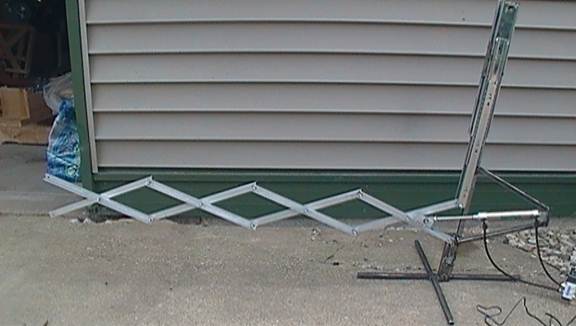
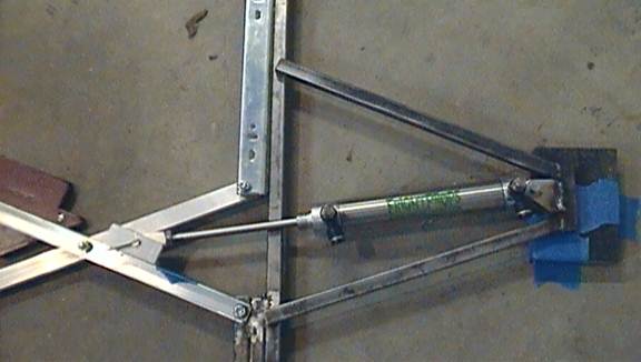
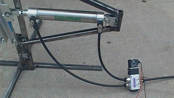
Lay your partially completed rig on the ground as shown and use tape to secure it to the ground or at least indicate exactly where it should stay (mark out its location, like a chalk outline. You want to keep it in the same spot every time you check a position for your cylinder).
You will need miscellaneous objects propped under the rig’s base, arm, and the cylinder end to keep the pieces level.
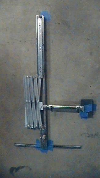
The horizontal length of pipe at the bottom is only to prop the end up and keep it level, as is the black block beneath the cylinder’s end.
Position your pneumatic cylinder (prop up its end so that it’s level) so that it is approximately perpendicular to the mast and about one inch bellow the mechanism’s center joints.
Use tape to mark exactly where the pivot bracket on the bottom of your cylinder is. Its flat edge should be kept parallel with the mast.
Place a piece of tape on the scissor mechanism to indicate where your cylinder’s foot rests.
Now extend your scissor rig to what you want to be its maximum extension. Make sure that you don’t extend it so far that it locks up.
By pulling, extend your cylinder’s rod to its full extent. Keeping the pivot bracket in its original location, place the foot installed on the cylinder’s clevis against the scissor mechanism’s arm.
What we are doing is simulating how the cylinder will push and pull the scissor mechanism. Look closely at the picture above and you’ll see that the tape on the scissor mechanism no longer matches up with the cylinder’s foot. This means that the cylinder is not in the right location to extend the scissor mechanism as far as we want to.
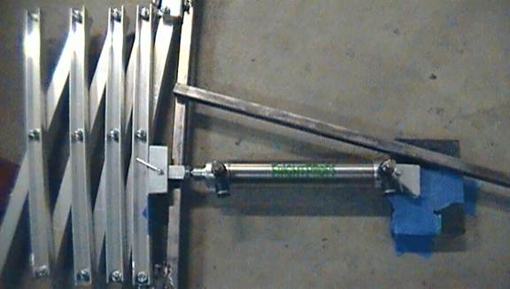
Retract the scissor mechanism and the cylinder rod and try again. Shift the cylinder up or down, making sure to move the tape indicating the cylinder’s pivot bracket position and it’s clevis foot position. Repeat extending the scissor mechanism and cylinder rod and see if the tape matches up this time.
Repeat that step until you find a “sweet spot” in which your clevis foot will not move from the taped spot when it extends or retracts.
When you find this spot, this is where we want to install the cylinder in respect to the rig.
Things to watch out for:
Notice that the cylinder is pushing against the scissor arm that is offset from the mast. The rod clevis’s pin is longer than the arm is wide, however, and it may still bump against the mast or the other half of the scissor arm when it moves back and forth. Either make sure that the clevis pin does not overlap the mast or second half of the arm when either fully extended or fully retracted, or install the clevis foot on the arm offset enough so the pin does not hit anything as it moves.
Step 11:
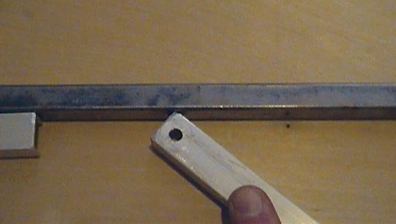
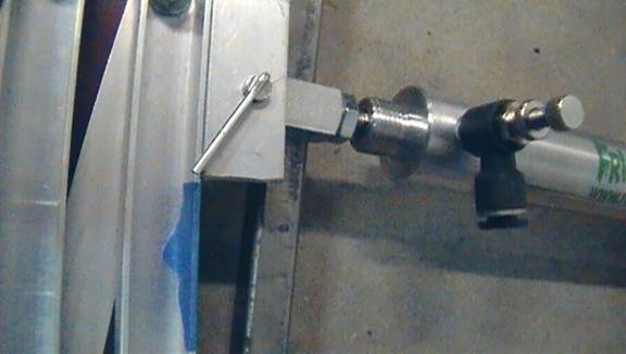
Now we measure our the arms to install in order to hold the cylinder’s pivot bracket in place relative to the rig. Line up one of your sticks of 1/2inch steel tubing and mark on it where it touches the pivot bracket. Take a flat edge and mark the angle of the pivot bracket’s flat edge so that after you cut this piece of tube down to size, the angled end will line up with the pivot bracket’s flat edge, as seen two pictures down.
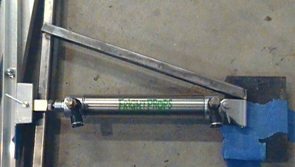
Use this piece of metal as a guide to make an identical piece. This will be the bottom support.
Cut a third piece without fancy edges to make the back of the support.
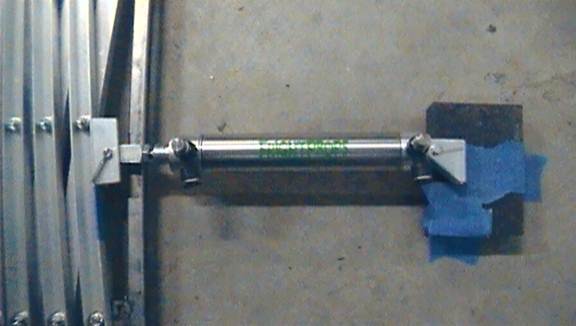
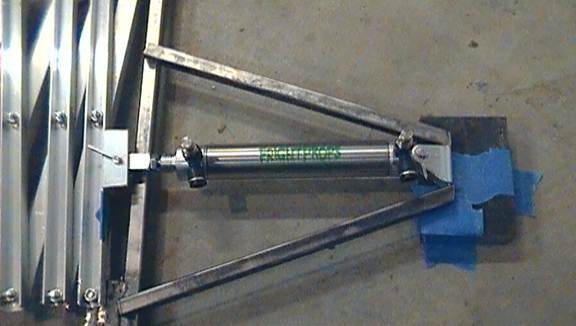
Step 12:
Weld these three pieces of square steel tubing together then weld the pivot bracket in place within them.
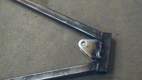
Notice that the bracket is sticking farther out one side than the other. This is the side that faces towards us in many of the pictures shown. The pivot bracket is wider than the 1/2inch steel tubing.
Remember the warning about the rod clevis pin striking the mast or arm if you didn’t offset it? By welding the pivot bracket further away from the mast than centered in the braces, we offset the cylinder and the rod clevis, helping us avoid that pin problem.
Step 13:
Reinstall the cylinder into the pivot bracket and reposition everything as it was before. Test it out, situate the pivot bracket until all the tape lines up whether it is extended or retracted.
Weld the supports in place against the mast.
Step 14:
Install the scissor mechanism from the rig and the clevis foot from the clevis. Line the foot up with the tape you last placed and clamp them to each other. With them affixed to each other, drill two holes through the two and use the 1/2inch bolts to bolt the foot to the scissor arm.
Reinstall the scissor mechanism to the rig and the clevis foot to the clevis.
Step 15:
The hard parts are over! All that’s left is to construct a base for the rig (we did not construct a base earlier because we needed the rig flat on its side for step 11).
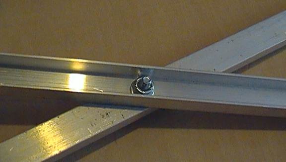
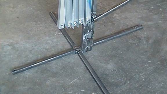
For this, simply take whatever 1/2inch steel tubing you have left and cut it in half. Drill a hole into each end of the two pieces then cut one of those pieces in half.
Weld the long piece of tube parallel with the direction the scissor mechanism will move back and forth, that is where all the force will go. Then take the two smaller pieces and weld them on either side of the long piece, creating a X-shaped base. Remember to keep the holes on the outside.
IMPORTANT: if you’ve extended the mechanism when it’s upright, you’ll have noticed that the scissor mechanism buckles downwards a little bit. This is natural, coming from the small amount of slack between bolts and holes. To compensate for this, do not weld the mast perfectly vertical. Instead, angle it back to aim the scissor mechanism upwards a little bit.
If you don’t weld it quite right, don’t worry. You can make up for this by placing blocks or spacers under it to tilt the whole rig.
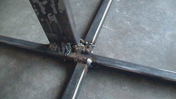
(please excuse the messy welds. Again, while being an experienced welder helps, even a mediocre welder can secure the pieces well enough for a rig like this)
This is not a stand-alone base. The purpose of the holes are for you to screw/bolt this rig onto a wider and more stable platform. Best option is to screw it onto a platform of wood, plywood or chip wood will work just fine.
Step 16:
Rig construction is done. All that’s left is to assemble the pneumatics kit. To do so, follow the instructions that came with said kit. Remember to use regulated valves going to the pneumatic. A 1 1/16inch bore pneumatic will supply more than enough force, and at full force might actually break the scissor rig. Be sure that the valves are letting very little air through when you first test it, to make sure the pneumatic isn’t working at full force and is in risk of destroying your rig.
Hook the solenoid to the pneumatic as instructed by the manual you should receive with it (if you lose it, go to Frightprops.com for it) and connect the air hose adapter. Solder the electric leads of the solenoid to an appropriate power source (either 12VDC or 110VDC, depending on which version you purchased).
In the picture bellow, a small red switch is installed in the circuit to test the pneumatic out. You can hook it up to a button, switch, or some sort of sensor to activate your pneumatic.

Step 17:
Attach your prop to the end of your rig and enjoy! You may need to customize an arm or an arm attachment so whatever prop you’re attaching will move as you want it. Remember that as the rig extends, the arms rotate. The top arm rotates downwards and the bottom arm swings upwards. Factor this in when deciding how to mount your prop for the best scare tactics.
Hook up the power source and an air compressor and you’re good to go!
FINAL NOTES:
- Remember that pneumatics can be dangerous if the right precautions are not taken.
- Make absolutely sure that the rig is receiving less than 120PSI at all times.
- When testing the rig for the first time, make sure all persons are at least five feet away and to the side of the rig (not behind or in-front), and that the area is clear around the rig.
- Make sure that the prop and the base platform are securely attached to the rig before activating it.
- Be sure to regulate pressure or enlarge the base platform so that the rig does not move from its spot when activated repeatedly.
- Inform everyone working around or with the rig about the dangers of it, and safe operation.
- When using this rig for an attraction, be sure that it is placed where it has no chance of physically striking someone, even if they wander from the attraction’s designated path. It is safer yet to regulate PSI to the minimal force required to flip your prop.
